Who doesn't want to know more about the air quality in their area?
Of course, you can find statistics on many websites, but where's the fun?
Living in Florida, there are many places to do this test. Tampa Hacker Space is located near a busy area. -4 / I-
275 overpass, we take advantage of the opportunities provided by space location.
The idea of pollution and adequate sunlight is the idea of a solar pollution monitor.
Our goal is to use a remote sensor to measure carbon monoxide in real time and then publish it to an interactive map after sampling.
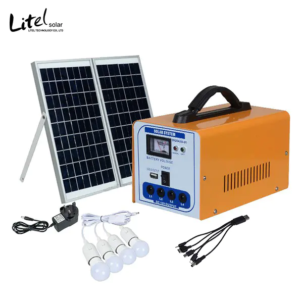
Of course, all of these are solar powered, using a 6-watt solar charger suite from the Voltiac system. A self-
Containing solution.
Let's put all the tools and components together and download the code / driver to use. Tools -
Soldering iron-Solder -
PC or laptop that can be programmed for your Arduino(or clone)
With a USB port prerequisite, get and install the driver for Digix from the following location: project code GitHub repo:parts:-
6 W solar charger kit, supplied by power system(-
Cloning of Aduino or Arduino with WI-Fi built in (
We used digistump version 1 digix. 0)-
USB to micro connector for Arduino power supply, which is provided with solar charger kit-
USB to Micro Connector for Programming Arduino(
Unfortunately, you can't use batteries with solar chargers. -MQ-
7 Carbon monoxide sensor from Sparkfun-
Sparkfun gas sensor adapter board-BUK553-100 Mosfet (N-
Channel logic level MOSFET, arbitrary n-
Channel level MOSFET processing 1 ampere)-
2 x 10 kOhm resistor-
Standby PC Board(
Weldable prototype plate)-
Head pin(
Sufficient processing for at least eight, the final number will depend on the number of sensors you want to connect, if you choose from this indicative extension! )-
1 x 2 inch x 1/4 inch round head square neck bolt(
We chose this bolt because there is a square under the mushroom head, which can be wedged into PVC to prevent rotation. -
3 x 1/4 inch nuts for body bolts-
1 x 1 inch 4 inch long PVC tube-
4 x 1 inch heat shrinkable tube 3/16 inch in size-
An orange 24 AWG wire 1. 5 meters long -
A black 24 AWG wire 1. 5 meters long -
A red 24 AWG wire 1. 5 meters long -
A yellow 24 AWG wire 1.
5 m long note: Although not required, we recommend four colors of connectors.
It can be exactly the same color, but using different colors helps avoid incorrect connections.
Install the driver on PC/Laptop from Digix for Arduino/Clone.
If you choose to use Digix, you need to follow the instructions on their website. (
Key libraries to ensure access to WI-Fi.
Following these steps will help test to ensure that you can also see it for later use in the project.
Ensure that you can see it by executing standard Arduino sketches.
We recommend using 01.
Basic knowledge, then choose to flicker.
This will ensure that you can program Arduino when it appears. Set up the Wi-
FI on the Aduno.
Follow the instructions on the tutorial links to ensure WI-
FI works on Arduino/Clone.
At the end of the document, they have a test sketch to run for testing.
It's Digifi, then the basic customer.
Click Play, it will run, and then turn on the serial monitor.
It says "press any key".
Enter any letter you want, and then click Send.
Watch the serial monitor to confirm that it is communicating. Setup Wi-
FI on Digix: It's time to create sensor shielding.
To this end, we will install the harvester.
The harvester needs to be aligned with the following Arduino pin position: +3. 3V (
Contact 1)+5V (
Contact 2)Ground (
Our Connection 3)Ground (
Our Connection 4)Voltage In (
Our Connection 5)Leave a Gap (
This is where Arduino has a space in its mother connector. (
Our Connection 6)A0 (
Our Connection 7)A1 (
Our Connection 8)A2 (
Our connection 9)
Install the first resistor.
The resistor will be connected to connector slots 7 and 9, close to A0 and A2.
MOSFET MOSFET on 7, 8 and 9 are installed on our circuit board.
The connection is: PIN1 on MOSFET(
Which door)
Align with slot 7(
Above, but not connected to a0)
Pin 2 on MOSFET(
Which is the drain?
Align with slot 8(
Located above, but not connected to A1)
PIN3 on MOSFET(
Which source)
Align with slot 9(
Located above, but not connected to A2)
Install a second resistor on the third joint.
Bring resistance to a convenient connection, at least 3 or 4 gaskets.
Install A0 to PIN1 MOSFET connections(
Which door)
Use yellow line.
Install two more connectors.
Pin 3 for MOSFET Installation(
Which source)
Pin 4 to the harvester(
Go to Arduino Ground)
Install the end of the resistance from step 7 to the ninth slot pin of A2 on the Arduino board.
Install a wire connection on the gas sensor adapter board. Each connection uses a wire of about 1 metre to weld the black wire to the ground. (Ground)
Weld yellow wire to b1, orange wire to A1 and red wire to h1(
This is the heater power supply.
Now that the connection is welded, insert the sensor into the plate itself.
Twist the four wires of the sensor to make it twist about two inches.
Slide on the heat shrinkable tube.
Heating the tube very carefully to make it shrink on the wire.
Start with the nearest position to the sensor.
Installation of Sensor Grounding Wire(the black one)
To MOSFET pin 2(
Which is the drain? .
Don't be fooled by this picture, it will bend!
The yellow wire of sensor B1 is installed on the resistor of slot 3, and the orange A1 sensor wire is installed on slot 1 of the harvester pin. (
This is Adonio 3. 3+)
Install the red H1 sensor wire on slot 2 of the harvester pin. (
It's Arduino+5)
Now connect the shield you just created to Aduno.
Be sure to start with slot 1 of Arduino 3.
3+, and make sure slot 7 ends at a0.
You may find that slots 7 to A0 are easier to queue for gaps.
At this point, you may need to install additional head pins that actually do nothing but provide stability on the board.
Cut a slot on PVC about the width of the body bolt(¼ inch)
One inch deep.
Remove the body bolts and install all three nuts.
At this point, slightly bend the sensor wire about an inch from the sensor.
Now slide the sensor into the PVC and face the slot that has just been cut.
After the sensor is placed, the round head and square neck bolts are placed behind the sensor, and the sensor is wedged into place.
Fixed round head square neck bolts by tightening a nut to PVC. The aim is to provide a moisture shield to prevent debris from easily affecting the sensor, while still allowing air flow to prevent air measurement from being fresh.
Open the Arduino sketch on your computer to ensure that Arduino is connected to a USB cable.
Now load the sketch onto your Arduino.
Open the serial monitor to ensure that it communicates with the sensor.
When it counts down to read, you should see a lot of debug text.
The system is currently set to read the following readings: the heater opens for 60 seconds and then moves to the middle range for 90 seconds. (
In the case of acquisition of readings, it must be done every five minutes between the two sampling cycles, as this is done in the next available free time period)
In the fifth minute of this free time, we read every 10 seconds.
We cut out the highest and lowest parts and then average the remaining parts.
This is to eliminate noise.
Now is the time to register and publish data!
You need to go to this URL and register your API key: Just create a quick account and the page will output the user ID, sensor ID, and API key that you will use in the following steps(
In your Arduino code).
It's time to get latitude and longitude for your Aduino code.
For this reason, we recommend using the following site because it is very easy to use: just enter your address and get the values created in the longitude and latitude boxes.
You will use them in the next step.
It's time to enter your registration information into your sketch code.
Find the line in Arduino's "Network and Location Information" section, download the new code as step 17, and test it.
Connect the power supply only USB from Voltiac to Arduino and from Voltiac battery to Arduino.
Connect solar panels to voltage cells.
Install it outside, inside, or anywhere! That's it!
You've already started running.
The biggest advantage of the power source of this project is that the voltage panel gives us 6 watts, the battery gives us 5 watts, and we consume 1 watt. -2 watts.
So in theory, we shouldn't dry up.
Complete ego-
Include power projects!
It runs all night and recharges during the day!