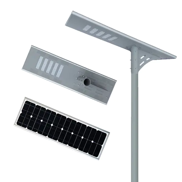
Solar street light installation diagram
The installation of solar street lights is basically the same as the installation process of traditional street lights, but there are differences, especially the installation of solar panels and batteries. Solar street lamp installation and construction process: lamp position selection, basic prefabrication, battery assembly, battery panel and support plus assembly, light pole assembly (threading, lamp installation, battery panel technical frame installation), hoisting, battery installation, controller installation , Light pole calibration position, acceptance and handover.
Selection of lamp position:
1. On-site testing, no obstructions around the lamp position. There is a lifting space during installation (whether there are high-voltage cables around, etc.).
2. According to the requirements of street lamp road installation specifications, the lamp position is fixed, and three lighting methods are used (single-side lighting, double-sided cross lighting. Jiangsu Naite Lighting Electric Co., Ltd. is engaged in the production and design of solar street lights, high poles Lamp manufacturer, 20 years of solar street lamp production experience, to create the most professional solar street lamp manufacturer, contact number: 13805257308., double-sided symmetrical lighting); the height of the lamp is determined, and the relationship between the width of the road and the way of lighting is determined; the distance between the lamps and the lamp The relationship between the height and the inclination angle of the illumination (usually about three times the height of the lamp).
Basic prefabrication:
1. To determine the size of the embedded parts, according to the data provided by the lamp pole factory, determine the relationship between the height of the lamp and the size of the embedded parts as follows:
Serial Number
Lamp height (m)
Basic size
(length*width*height) mm
Diagonal size of embedded parts (mm)
Screw specifications
Picture number
Remarks
1
4
400×400×800
220
M18
2
4~6
500×500×1000
280
M20
3
6~8
600×600×1400
360
M24
4
8~12
800×800×1500
400
M28
5
2. Dig the pit, determine the size of the pit according to the fundamental size, and reserve the location for the battery to be buried; see the fundamental diagram for details
3. Basic prefabrication. When prefabricating the foundation, the concrete label shall be carried out according to C20. At the same time, the basic vibration mechanism shall be used to vibrate and compact to ensure the quality. When pouring the concrete, be careful not to pour the concrete on the screw rod, so as not to affect the installation speed. When pressing the threading pipe, press it according to the requirements of the drawing and make sure that no concrete is injected into the pipe. The distance between the lower nozzle position and the root surface is 250mm. Level the basic profile and test it with a degree meter to ensure the accuracy of the four feet.
Preparatory work:
1. Tool preparation, according to work requirements, prepare the corresponding tools, and make a list (the model and quantity should be indicated on the list), and prepare according to the tool out list table.
2. Material preparation, prepare the materials according to the purchase list, and check (quantity, specifications, etc.) one by one to confirm the accuracy;
Installation work:
1. Assemble the battery, check whether the battery capacity is the same as the design configuration sheet, (if multiple units are connected, please confirm the parallel series connection, and the parallel battery cannot exceed 4 units). When wiring the battery connection line, pay attention to the stability of the welding point of the connection line nose. Put the connected battery into the battery incubator, seal the incubator, and pay attention to fasten the screws everywhere in the incubator during assembly to avoid dew;
Place the assembled battery box in the battery pit and cover it (or directly bury it in the soil); it is best to choose a good day when the battery enters the pit; after entering the pit, lead the connecting wire out of the pit. , Test whether the voltage is normal, or check it.
2. Battery board assembly, before assembling, move the battery board bracket and the light pole to the base, fix the battery board on the shelf with screws, and wire the battery boards in series according to the requirements, and test after the wiring is closed. , To ensure that the voltage meets the installation requirements. Normal weather environment: 12V system battery board system test voltage cannot be lower than 18V, 24V system battery board test voltage cannot be lower than 36V. If it is less than the requirements, check whether the board voltage meets the requirements.
We are here to help you! If you close the chatbox, you will automatically receive a response from us via email. Please be sure to leave your contact details so that we can better assist