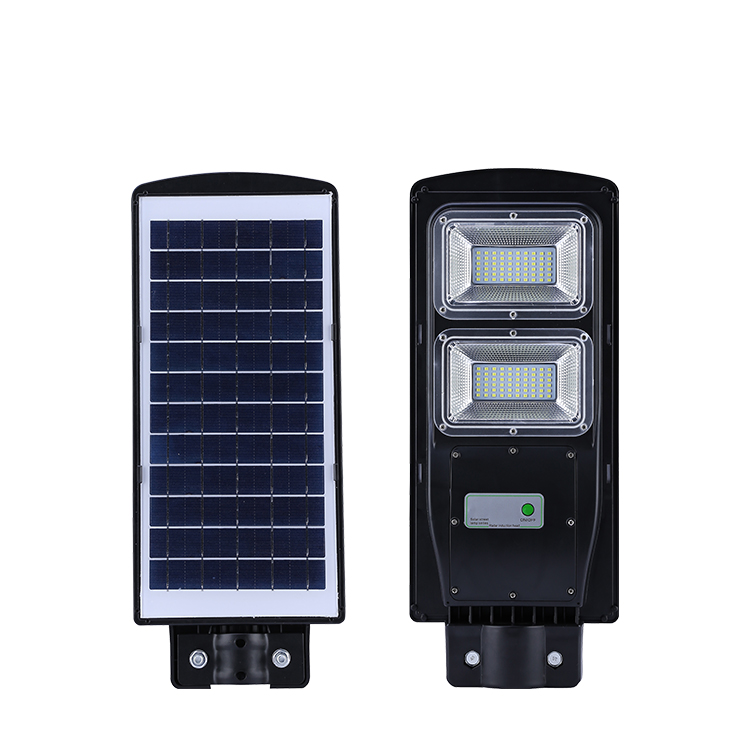
Hello, friends. Thank you for your support for my previous projects. Today I want to make life "instructive" and save money and time.
This is a "How to Make Automatic Solar Night Lighting" course.
The device charges during the day and works automatically at night. It has three circuits.
A switching circuit.
Solar battery charging circuit and LED night light switch circuit are the important parts of the system.
To make the required switching circuit 1)IRFZ44 MOFSET2)
150 K ohmic resistor(
See Step 3 for more details. 3)
32 pin PCB connector 4)Wires5)LDR6)
The printed circuit board bordfig display circuit AM uses a long two-core coated wire to connect the LDR to the main circuit.
This will help to avoid unnecessary light from other sources. This is the most important step in circuit design.
The calibration of the circuit is helpful to improve the sensitivity of the dark sensor. LDR is an important part of the circuit.
It will act as a dark sensor.
There are two ways to calibrate LDR, one is pre-calibration, the other is post-calibration. In pre-calibration, we use a resistor with a predicted resistance.
In post-calibration, we use a variable resistor, and in the final stage we use a pre-calibration calibration circuit, because it is simple in India, and the cost of variable resistors is 5 to 10 times higher than that of a single resistor. For pre-calibration, you need to find the correct resistance.
First, you need to find the R Max and R min of the ldr, connect the LDR to multiple centers and find the maximum resistance. (R max)at day time.
Repeat this step at night to find the minimum resistance(R min)
In my example, r Max is 600k and R min is 2k. In order to find the resistance we need, I used the divider equation V out = V in x. (R2/R1+R2)
V out = mofset gate V in = power supply voltage(12V)R1 = R min (
2,000 or 2,000 ohms)R2 = R1 (
I use 150 K or 150,000 ohm resistors. 12x (
2000/2000+150000)= .
150V, which means that the mofset will remain closed, is now tested with R max.
Is it 600K or 600000 ohm12x? (
2000/2000+600000)= 9.
5 volts, so the mofset turns on and it turns on the light. I use a 12-volt-7-ampere battery power supply and a 12-volt-2-watt LED as the light source.
To recharge the battery, I used a 12V 6W solar panel.
In order to reduce the cost, I use DC-DC buck converter as charge controller.
It can increase 12V to 14V and prevent voltage flow with a large capacity of Dior. After a month of testing and running, I found that these solar panels could not be fully charged. You might want to know how the circuit works without any overcharge protection.
Due to low current, the battery takes 18 hours to fully recharge, but sunlight can only provide 12 rooms at most.
In short, switching circuits and LED lights consume 10 to 12 W of battery power at night, while solar panels supplement battery power during the day.
It's a bit tricky, but it works!
The circuit of the whole system is shown in the figure. If everything works, the circuit turns on the light at night, closes the battery during the day and charges it.
